
|
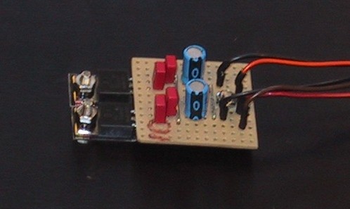
Battery Eliminator Circuit
|
 |
|
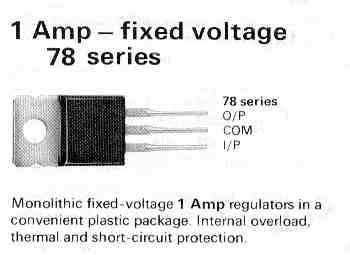
These chips come in all different varieties and the ones we are interested in are the:-
|
 |
|
These regulators depending on manufacturer and type have a maximum input voltage of between 20 and 40 Volts. You can buy them readily in the UK from:-
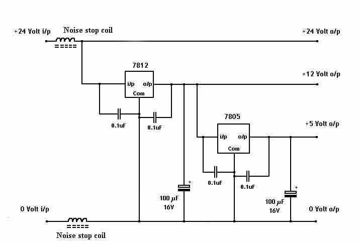
So that our circuit will work with all types of regulator we shall do it in two stages. First regulate down to 12 Volts then regulate that down to 5 Volts. This has the added bonus of providing the robot with a 12 volt supply as well as eliminating the chance of any interference on the supply rails to the receiver. If you want to run the circuit from a 12 Volt supply then simply leave
the first stage of regulation out. |
 |
|
|
|
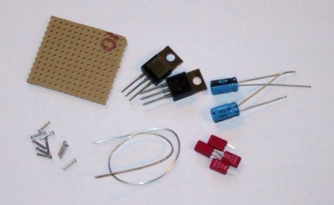
OK so now to start you will need:-
|
 |
|
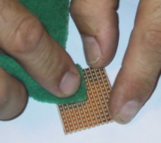
First cut the Vero board to size, then clean the underside with a
scouring pad. Don't miss this bit out as it makes soldering much easier
later on. |
 |
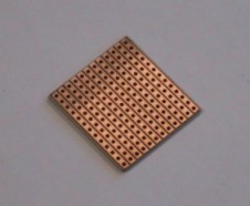 |
File the edges of the board clean, this makes for a much nicer looking
job. |
|
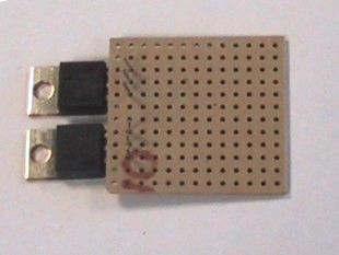
Carefully bend the legs of the regulators and fit them to the
board. |
 |
 |
Solder the regulators in taking care not to leave any solder bridges
between the tracks. |
|
Next add the capacitors, tinned copper wire links and Vero
pins. |
 |
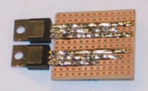 |
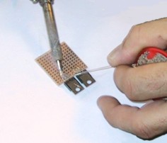
Build up the tracks with solder (Not too much) so that they can handle
the current.. |
|
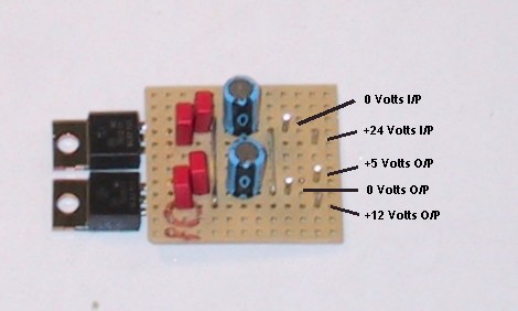
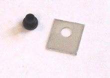
The tabs of the two regulators are internally connected to 0 Volts, it
is a very good idea to electrically isolate them from the metalwork with a
mounting kit (Mica Washer and plastic ferrule), thus reducing
interference. The regulators must be bolted down to a heatsink to prevent them
overheating. The heatsink can be the metal box you house your receiver
in. |
 |
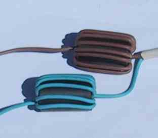 |
Make the noise rejection coils with a minimum of 10 turns through a
ferrite former. |
|
Specifications
The maximum input Voltage depends on the specific chips used
The minimum input voltage is about 15 Volts
The maximum Current also depends on the chips used |